Vertical Profiler 2024
This was our first complete attempt at a profiler that could run a mission on its own and return the recorded data to a base station.
At a glance
Project Result
The profiler proved the basic buoyancy, logging, and LoRa architecture. Its cramped packaging and unreliable first radio choice also gave me a specific list of problems to solve in the 2026 redesign.
- Season
- 2023–2024 MATE ROV
- Control
- State-based descent and ascent
- Result
- Architecture proven; redesign needed
README
Project Writeup
Overview
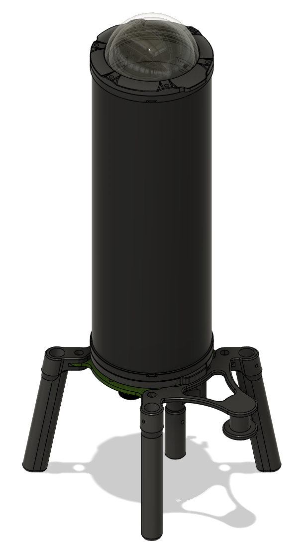
I worked on this profiler during the 2023–2024 MATE ROV season with The Rays. It was our first attempt at a float that could run separately from the ROV, record pressure and time data, then send the run back to a base station.
The project did not end with a polished design, but it proved the main architecture. It also exposed the packaging, communication, and control problems that I wanted to solve in the 2026 profiler.
Goals and Requirements
The float needed to operate on its own and fit the batteries, sensors, electronics, and buoyancy engine inside one watertight enclosure. The main requirements were:
- Operate independently from the ROV
- Keep the electronics sealed and dry
- Record pressure and time during a profile
- Start from a separate base station and return the recorded data
- Include the required power protection and fuse
- Meet the MATE ROV rules for a non-ROV device
Planning the System
This was one of the first projects where I tried to plan the complete system before focusing on individual parts. We divided the profiler into mechanical, electrical, software, communication, and buoyancy-control work, then used shared documents and a schedule to keep those pieces connected.
The enclosure was an early decision because it controlled almost everything around it. We compared size, sealing method, cost, penetrator options, and how difficult each enclosure would be to modify. I learned that a part can satisfy the pressure requirement and still be a poor choice if it leaves no practical way to assemble or service the system.
Mechanical Design
The profiler used a compact cylindrical layout. A custom internal structure held the batteries, electronics, actuator, and buoyancy hardware together inside the enclosure.

Fitting everything inside took several revisions. Antenna clearance, fuse access, battery placement, wiring, and the order of assembly all competed for the same small volume. Some of the final complexity came from solving those problems after parts had already been selected. That was a major reason I defined interfaces earlier on the next profiler.
We also made custom aluminum spacers, linkage parts, and external mounts. The parts were cut, cleaned, and anodized for corrosion resistance.
Buoyancy Engine
The buoyancy engine changed the profiler's displaced volume with a syringe-style mechanism. Extending or retracting the mechanism made the float more or less buoyant.
The control sequence was intentionally simple. After a start command, the profiler descended while recording pressure and time. It then switched to ascent and returned the data to the base station at the end of the run. This did not hold depth like the later controller, but it was enough to test the buoyancy-engine idea and the full mission sequence.
Electronics and Communication
I designed a custom PCB to reduce point-to-point wiring and fit the power and control hardware into the available space. The board connected the microcontroller, pressure sensor, real-time clock, temperature probe, buck converter, bottom switch, motor control, and external power switch.
The original communication system used nRF24 radios. They worked in basic tests but were not reliable enough as the project grew. We changed to SparkFun SAMD21 Pro RF LoRa boards, which gave us a more dependable connection and let development continue.
The power system used two 9 V batteries, a series/parallel switching arrangement, a buck converter, and a 2 A fuse. I sized the fuse from the expected current of the motor, control board, and sensors.
The finished system had two parts. The float handled the mission, sensor readings, and radio messages. The base station used a second Pro RF board, a start button, an OLED display, and a USB connection to a computer.
Software
The float software handled standby, start-command detection, pressure and time readings, the descent and ascent sequence, and transmission of the recorded data. The base station checked the radio connection, started the run, received the data, and displayed status information.
I chose a state-based sequence because it matched what this early hardware could support. Adding a more complicated controller would not have fixed the packaging and communication issues we still needed to understand.
Problems and Revisions
The most persistent mechanical problem was serviceability. We could fit the required parts, but small changes to the antenna, button, batteries, or wiring often affected the rest of the assembly. The custom PCB helped, although it arrived after several layout decisions had already become difficult to change.
Communication was the other major problem. Replacing the nRF24 modules with LoRa boards cost time, but it was better than continuing to build around a connection we did not trust.
These problems changed how I approached the next design. I wanted less loose wiring, easier access, earlier interface decisions, and a controller that could be tested outside the pool.
Final Result
The 2024 profiler combined a custom PCB, embedded software, a LoRa base station, sensor logging, and buoyancy control in one working system architecture.
Its most useful result was a specific list of what needed to improve. Those lessons became requirements for the 2026 profiler instead of being left as general ideas for a future redesign.